
White Paper: The Safety Factor Trap
To see images and tables, download the white paper PDF.
How do we prevent compounding safety factors and oversizing from causing shortened valve lifespans and expensive pipeline system failures? To evaluate the impact of oversizing check valves and control valves, we need to look past generic flow charts and examine the destructive macro and micro environments created by using a valve much larger than needed. This issue can manifest from several scenarios. For example:
• When a large-diameter butterfly or eccentric plug valve is forced to operate continuously at a highly restricted open position, it ceases to function as a control valve and becomes a cavitation-inducing high-velocity jet, with the potential of damaging the valve and system components.
• An oversized valve operates at low opening angles, and thus has a very short closing time. This creates a situation where system-wide water hammer is unavoidable.
• When the powered actuator, sized for the entire opening range of the valve, is forced to only use a tiny portion of that opening range to control the flow, it can potentially hunt for the desired flow rate, wearing out motors and bearings prematurely.
A simple solution to prevent problems caused by oversized control valves and still maintain capacity for peak demand is to build duality into the control system. Adding a smaller control line alongside a larger isolation line is the easiest way to satisfy both design requirements — a smaller loop for everyday demand and a potentially larger second loop for worst-case, high-demand events.
Check valves are also vulnerable to being oversized, but in a different way than control valves. Both traditional swing check valves and resilient hinged check valves need adequate flow to prevent damaging internal components with excessive oscillation. There are less options for check valves to accommodate lower flows, but some designs will tolerate this situation better than others. The best solution for this situation is also a secondary line sized for proper flow.
In the next few pages, we will discuss why both control valves and check valves have specific flow needs and what can be done to mitigate or completely avoid future problems when engineers are left with no other choice than to oversize those valves. Since the municipal water industry uses primarily butterfly valves and plug valves for flow control, we will limit the discussion to those two types of control valves.
THE COUNTERPRODUCTIVE EFFECT OF STACKING SAFETY FACTORS
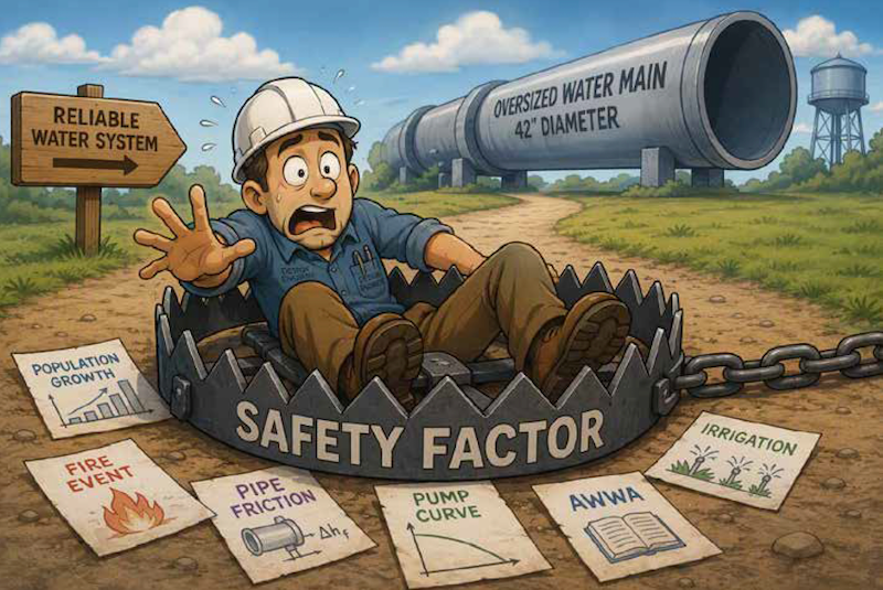
The industry norm is to stack safety factors when designing water systems. The reasons for doing this are valid. Water systems need to last for decades without requiring rebuilds and additions to keep up with projected demands. Engineers are expected to design for every possible scenario and keep systems working without the public noticing, especially in emergencies. Reliability cannot be understated.
Key metrics used to size the system often involve worst-case scenarios. City planners give optimistic projections of population growth. Peak flow is based on high use during heat events and high demand irrigation. The American Water Works Association also has standards for sizing pipelines and control valves that engineers apply when designing water systems. Additional buffers are added for pipe friction, pump curves and preventing low pressure contamination. All this is added to the non-negotiable water volume needed during fire events.
Every demand and standard applied to the design complicates an engineer’s decision on sizing. When it comes to safety factors, “more is better” typically prevails. However, more is not always better with control and check valve sizing. When safety margins add up at the valve sizing stage, there is typically a large mismatch against standard daily operational realities. Frequently, the choice is to install valves too large for current demands and “make them work”.
Both control valves and check valves have specific flow requirements that complicate the solution to an oversized system. All the needs mentioned above do not allow a localized line reduction to accommodate a smaller valve appropriate for daily flows. Next, we will cover the specific problems oversized valves experience and what solutions are available to accommodate a very large range of flow.
THE PHYSICS OF CONTROL VALVE FAILURE (THROTTLING & CAVITATION)
A fluid control butterfly valve is designed to operate best in a window from 20% to 80% open. An ideal control scenario would be operating from 50% to 70% open. In an oversized situation, large valves are commonly set to a control position of less than 20% open, sometimes as low as 5% open.
Operating below 20% open is considered “The Danger Zone” for cavitation. When a large diameter butterfly or eccentric plug valve is forced to operate continuously at a highly restricted open position, it ceases to function as a control valve and instead becomes a cavitation inducing high-velocity jet. Fluid forced through this narrow opening experiences an intense velocity spike and a sharp pressure drop. This large pressure drop can immediately cause cavitation, damaging the valve and nearby system components.
Cavitation is a highly destructive process that happens when a liquid's speed increases so fast that its internal pressure drops below its boiling point, causing tiny vapor pockets to flash into existence. As these bubbles travel down the pipeline into an area of higher pressure, they instantly and violently collapse inward on themselves. This rapid collapse produces microscopic liquid jets and intense shock waves that continuously slam against the valve components and the inside of the pipe.
Over time, these millions of tiny explosions physically chip away at the metal, causing severe pitting damage, heavy vibrations, and a distinct roaring noise that sounds like gravel rattling through the valve. In valve undersizing scenarios, operating above 80% open removes any control margin. If the demand goes up, the valve will hit fully open quickly and lose the ability to control the flow.
TRANSIENT GENERATION AND THE EFFECTIVE CLOSURE ERROR
Allowing at least 60 seconds to close a valve from the fully open position is an industry standard for a safe flow deceleration ramp. With 60 seconds for a full cycle, it will only take a few seconds to close a valve from 5% open. When evaluating hydraulic shock risks, this tiny three-second window carries the highest potential for danger. Because the valve disk or plug has already restricted 95% of the waterway, the available flow path is exceptionally small. Consequently, sealing the remaining gap during only three seconds of travel forces the water velocity to a dead stop almost instantly. This sudden loss of momentum transforms the remaining kinetic energy into a concentrated pressure surge or hydraulic transient.
In fluid dynamics, a hydraulic transient is the scientific term for water hammer. This phenomenon represents a brief, erratic shift in system pressure that happens whenever the steady velocity of flowing water is forced to change abruptly. Because liquids are nearly incompressible, slamming a valve shut or experiencing a sudden pump failure forces the water's forward momentum to instantly convert into raw kinetic energy. This abrupt halt triggers a violent shockwave that races back and forth through the piping network at the speed of sound. In everyday plumbing, this transient energy expresses itself as a sharp, metallic rattle or loud banging in the walls. However, in large-scale water networks, these sudden pressure spikes can easily overstress materials and system components.
The water hammer caused by an oversized valve can inadvertently trigger structural failure elsewhere in the municipal grid. Water hammer, or even just large pressure spikes, has many negative effects on water systems, including fatiguing pipeline walls, cracking air valve bodies and floats, and pushing monitoring equipment beyond its limits.
VALVE AUTHORITY AND DISTORTION OF FLOW CONTROL
When a valve is too large for a pipeline, it suffers from a condition known as poor valve authority. In simple terms, valve authority is a measure of what is actually in charge of the water flow — the valve itself, or the friction of the surrounding piping network. This can also be referenced as the valve controllability, control effectiveness, control sensitivity, or control range utilization.
A control valve with good authority acts like a smooth dimmer switch, where turning the knob slightly gives you a predictable, matching change in light. An oversized valve behaves more like a faulty dimmer switch that jumps from pitch black to super bright with the slightest touch.
To achieve good valve authority, engineers size a control valve to stay between 20% and 80% open when controlling flow rates between their minimum and maximum flows. A control range dipping below 20% open means the valve is oversized. A control range staying completely below 20% open makes accurate control very difficult.
When a smart electric or pneumatic actuator is paired with an oversized valve, the system’s control loop becomes unstable. If the system detects a minor flow deficit, it signals the actuator to open slightly. If the valve is working in a very narrow 0%–20% zone, even a 2% movement causes a massive flow surge. The system overcorrects, telling the valve to close, which triggers continuous actuator “hunting”. This constant cycling accelerates packing wear, strains gears, and leads to premature actuator failure.
SOLUTION
A simple solution to this challenge is using a dual line strategy when designing the control valve section of the system. Example: A 36” valve size is calculated to be necessary due to the system's anticipated peak demands, fire flow, and all other safety factors. However, standard daily demands only require 25% of the valve's optimal capacity.
Solution: Implement a dual stage design to handle both emergency/peak flows and daily demands.
• Line A: A large 30” main isolation valve, with an on/off actuator*, that remains fully open or fully closed, operating only during peak fire conditions or emergency bypass scenarios.
*This may need to be a modulating actuator if more accurate control at high flow is needed.
• Line B: A smaller 12” to 16” valve installed in a parallel bypass line, sized to remain at high authority during the daily flow.
TOTAL COST OF OWNERSHIP
The additional bypass line, with a smaller valve and additional actuator still has a high upfront cost, similar to just one large valve and one large modulating actuator. However, the repeated costs of replacing a large valve and/or actuator on a short maintenance cycle heavily outweighs the larger upfront costs. This doesn’t consider the additional maintenance costs due to potential line damage from water hammer or pressure surges.
| Metric | Traditional Oversized Design (e.g., 36" Valve + Modulating Actuator) | Optimized Design (e.g., 30" Valve + 16” Bypass) |
|---|---|---|
| Initial Asset Cost | High (larger valve body, larger actuator required) | High (smaller main valve with on/off actuator, additional secondary line and actuated valve) |
| Maintenance Cycle | Short (3-5 years due to cavitation/actuator hunting) | Long (15-20 years operating in stable flow zones) |
| Energy Consumption | High (persistent actuator hunting) | Low (smooth, less frequent positioning) |
| Surge Risk | High (abrupt closure) | Low (predictable closure ramp) |
THE CHECK VALVE DILEMMA
Check valves pose a slightly different problem when oversized. Both standard swing check valves and resilient hinge check valves require a minimum of 5 FPS flow rate to properly hold the disc in the open position. This higher flow rate pins the disc against the body or open stop, which prevents the disc from oscillating in the flow. A flow rate lower than 5 FPS allows the disc to oscillate, sometimes intensely. This can wear out internal components quickly and cause premature failure of the hinge mechanisms.
FPS Velocity Equation:
The average velocity of fluid flow within a pipeline is calculated using the standard volumetric conversion formula:
V = (0.408 x Q) / d2
• V = Mean fluid velocity, measured in feet per second (FPS)
• Q = Volumetric flow rate, measured in US gallons per minute (GPM)
• d = True inside diameter (I.D.) of the conduit, measured in inches (in)
When a check valve is oversized and the standard daily flow rate remains below 5 FPS, the disc will continuously oscillate in the flow. Municipal check valves on the market today are not designed to handle continuous oscillation and the lifespan of the components will be significantly compromised if the disc is always oscillating. However, the reduction in lifespan of the hinge and disc components is difficult to quantify without knowing the exact oscillation rate. We do know the wear compounds with time due to loosening components allowing greater oscillation, potential slamming, and eventually seat leakage.
SOLUTIONS
One partial solution to help extend the lifespan of an oscillating check valve is to install a KEN-FLEX™ style resilient hinge check valve. While this is not a full remedy for this situation, it is the easiest way to reduce the maintenance costs due to the increased wear.
A KEN-FLEX™ check valve has a one-piece resilient hinge that inherently withstands oscillation better than hinge components of a standard swing check valve that are continuously turning a shaft back and forth. The KEN-FLEX™ design also eliminates the use of packing around the hinge shaft that will wear out prematurely with oscillation and produce leaks. When resilient hinge replacement is needed, the process for a KEN-FLEX™ is much simpler than a standard swing check valve with only one part to replace after the cover is removed.
A permanent solution goes back to the same solution for an oversized control valve. A smaller bypass line can be added to a system, producing the proper flow rate needed for a check valve during standard daily demands, and the larger main line only being used in high-demand situations. This may require additional isolation valves to control the flow of each line, which adds to the initial costs, but still pays for itself over the life of the system.
TOTAL COST OF OWNERSHIP
When a check valve is used in conjunction with the control valve bypass line, the payback on a bypass line quickly multiplies. A larger check valve would still be installed on the main line, but oscillation would be very limited, as the main line would only be used during high demand/flow.
| Metric | Traditional Oversized Design (e.g., 36" Check Valve) | Optimized Design (e.g., 30" Check Valve + 16” Bypass) | Optimized Design Within Control Valve Bypass (e.g., 30" Check Valve + 16” Bypass) |
|---|---|---|---|
| Initial Asset Cost | Medium (larger valve body) | High (smaller main valve, but requires additional valve and secondary line) | Medium (smaller main valve, additional valve, but secondary line already exists) |
| Maintenance Cycle | Short (2-3 years due to disc oscillation) | Long (8-10 years operating in stable flow zones) | Long (8-10 years operating in stable flow zones) |
| Failure Risk | High (unpredictable wear) | Low (predictable wear) | Low (predictable wear) |
CONCLUSION
With so many factors adding to the predicted capacity needs of a water system, it is easy to oversize the system's supply lines, control valves, and check valves. While stacking safety factors during line and valve sizing seems like the “safe approach”, an oversized control valve can create long-term operation risks from cavitation and water hammer damage. An oversized check valve can wear our prematurely or fail unpredictably. Rightsizing infrastructure, including valves, is the first step to reducing maintenance costs and protecting pipeline integrity.
Once a control or check valve is right-sized, but is still oversized for daily flow, a different approach must be taken to minimize future costs and downtime. The simplest solution to the valve sizing problem is to add a bypass line with properly sized valves, while still maintaining the functionality of the system with large main valves, to be used only during occasional high-demand events.